Piezoelectric Tensor Rotation for PFM
Piezoresponse force microscopy (PFM) is often interpreted using a small number of effective coefficients, such as a vertical response and a lateral response. However, the intrinsic piezoelectric response of an anisotropic material is a tensor. This means that the coefficient observed by PFM depends not only on the material itself, but also on how the sample coordinate system is oriented relative to the laboratory coordinate system of the AFM.
Why PFM needs tensor rotation
In standard Voigt notation, the converse piezoelectric effect can be written as

where i=1,2,3 is the electric-field direction and J=1,2,3,4,5,6 is the strain component. The piezoelectric tensor is therefore commonly written as a 3×6 matrix
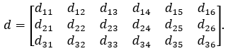
The tensor d is usually defined in the sample frame. For a crystal, this may be the crystallographic coordinate system. In contrast, PFM measurements are made in the laboratory frame. The lab axis 3 is normally the surface-normal direction, approximately aligned with the electric field applied by the AFM tip.
For a fixed PFM geometry, the experiment does not directly access all 18 tensor components. The vertical PFM signal is mainly associated with

while the lateral or torsional PFM signal is associated with one of the shear coefficients,

depending on how the cantilever direction is defined relative to the lab axes.
Therefore, a single sample orientation gives access only to a limited projection of the full tensor. When the sample is rotated, the original sample-frame coefficients mix into different lab-frame coefficients. Tensor rotation is required to determine which intrinsic coefficients contribute to the measured vertical and lateral PFM responses after a given sample rotation.
The central transformation
Let d be the piezoelectric tensor in the sample frame, and let d^lab be the same tensor expressed in the lab frame. The tensor transformation can be written compactly as

Here, A is the 3×3 rotation matrix acting on the electric-field index, and N is the corresponding 6×6 strain transformation matrix acting on the Voigt strain index. The matrix N is built from products of the elements of A, because strain has two directional indices
This equation is the key link between sample orientation and the PFM-accessible lab-frame coefficients. A measured coefficient such as d_33^lab is generally not equal to the intrinsic sample-frame d_33. Instead, it can contain contributions from several sample-frame coefficients, such as d_33, d_31, d_15, and others, depending on the symmetry and orientation.
Euler angles: active and passive views
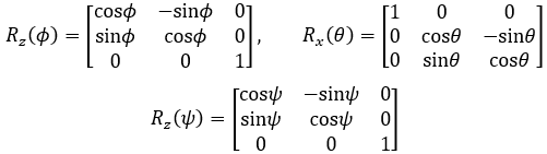
A general three-dimensional orientation can be described using a z-x-z Euler rotation sequence3. For active rotation, the rotation matrix is written as

The individual rotation matrices are
There are two common ways to describe the same relative orientation: active rotation and passive rotation.
In active rotation, the laboratory frame remains fixed while the sample is physically rotated. This is often the most intuitive view for PFM, because the AFM tip and cantilever remain fixed and the sample is the object that is repositioned. Using the moving sample-axis interpretation, ϕ first rotates the sample around its original sample axis 3 and sets the azimuthal direction of the subsequent tilt. This generates a new sample axis 1. Then θ rotates the sample around this new sample axis 1, tilting sample axis 3 away from the lab axis 3 and generating a new tilted sample axis 3. Finally, ψ rotates the sample around this new tilted sample axis 3, setting the final in-plane orientation. Thus, for active rotation, ϕ controls the azimuthal direction, θ controls the tilt angle, and ψ controls the final in-plane rotation.
In passive rotation, the sample frame remains fixed while the laboratory coordinate system is rotated. This convention is common in crystallography and tensor-transformation literature. The passive transformation is the inverse of the active transformation:

Using the moving lab-axis interpretation, ψ first rotates the lab coordinate system around its original lab axis 3 and sets the azimuthal direction of the subsequent tilt. This generates a new lab axis 1. Then θ rotates the lab coordinate system around this new lab axis 1, tilting lab axis 3 relative to sample axis 3 and generating a new tilted lab axis 3. Finally, ϕ rotates the lab coordinate system around this new tilted lab axis 3, setting the final in-plane orientation. Thus, for passive rotation, ψ controls the azimuthal direction, θ controls the tilt angle, and ϕ controls the final in-plane rotation.
The active and passive descriptions are inverse viewpoints of the same relative orientation. The important point is to keep the convention consistent when calculating d^lab=AdN.
Practical implication for PFM
PFM does not measure an isolated intrinsic tensor component unless the sample axes are aligned with the lab axes in a special way. In general, the measured vertical and lateral signals are lab-frame effective coefficients. By rotating the sample and calculating the corresponding tensor transformation, one can determine how the intrinsic piezoelectric coefficients are projected into the measurable PFM response.
This is especially important for anisotropic crystals, non-standard crystal cuts, tilted domains, biological fibrils, and other materials where the local material axes may not be aligned with the AFM measurement geometry.
In short, tensor rotation provides the bridge between what the material intrinsically is and what PFM actually measures.
References
Nye, J. F. Physical Properties of Crystals 1957.
Kalinin, S. V.; Rodriguez, B. J.; Jesse, S.; Shin, J.; Baddorf, A. P.; Gupta, P.; Jain, H.; Williams, D. B.; Gruverman, A. Vector piezoresponse force microscopy. Microsc Microanal 2006.
Safko, J.; Goldstein, H.; Poole, C. Classical mechanics. 2002.
Quisque iaculis facilisis lacinia. Mauris euismod pellentesque tellus sit amet mollis.